

A look Behind the Scenes: ECU Testing with XCP support
- By 0
- June 15, 2020
In most cases, it is actually sufficient to look at the ECU’s inputs and outputs to functionally test a component (Figure 1). However, this becomes difficult when state machines are used in the ECU. Their current states can only be derived indirectly by their effects at the ECU’s outputs. In the case of sensors whose values are not transmitted over the network system, it is also very difficult for the test engineer to localize errors to the software interface. From outside the ECU, it is not clear exactly where the sensor value was incorrectly processed.
Different methods that offer access to internal ECU data are used, depending on the phase of ECU development. In early phases, for example, internal ECU values are often output in so-called “reserved development messages” (Figure 1). For the functional developer at a supplier, this is an effective and quick method that precisely targets a specific objective. However, these supplemental messages must be removed for later development phases, especially for system integration and series production. They induce additional bus load, and in the worst case they might even collide with messages of other system components. Another way to access internal values is through diagnostics (Figure 1). Some information is available directly via diagnostics, e.g. diagnostics offers access to fault memory. Special diagnostic services are also provided to read the required values from memory. The advantage here is that a standardized access method is used. The only precondition is full integration of the diagnostic driver; this is generally provided in today’s ECUs. The disadvantage of this method is that a lot of unnecessary diagnostic protocol information is transmitted along with the actual measured values, and this adds load to the network system interface. A data flow analysis of many values is not possible, especially since the measured values do not contain time stamp information.

XCP For Test Access
If network interface load needs to be kept low, an alternative is to use a calibration protocol. Originally, such protocols were developed for the ECU calibrator. They let calibrators modify parameters or characteristic maps in the ECU to optimize their algorithms. With the XCP protocol standardized by ASAM, the user can read individual values directly from the ECU as needed. The protocol can also periodically supply a defined set of measured values from the ECU via so-called Data Acquisition (DAQ) lists. The XCP protocol was defined for efficient provision of data over the network medium. As an example, after configuration the DAQ lists can be transmitted in response to a single identifier from the test system. In addition, measurement times of the DAQ lists can be synchronized to internal ECU processes. Automated test systems place similar requirements on the system. Use of the XCP protocol makes it possible to integrate internal values in test sequences without excessive loading of the ECU or the network system used. Another reason that a widely used standard like XCP is ideal is that it is very easy to configure in the tool chain. All necessary information is already in the A2L file such as internal program memory locations with their names and communication parameters. Depending on the development environment, the A2L file is either automatically generated, or it may need to be generated in a separate step from the linker-map information. In the test tool, the user only has to configure this file once for each ECU used in the test. In a second step, the user selects the symbols needed for the test sequences from the A2L file.

CANoe Option .AMD/XCP
Option .AMD/XCP supplements the CANoe test tool from Vector with the convenient option of reading and writing internal ECU values. Besides supporting the XCP standard, it also supports the previous protocol CCP. Once the A2L file has been configured and the necessary values selected, CANoe automatically acquires them and maps them as system variables. The user can then use these variables in any of the testing tasks. Besides offering access to ECU inputs and outputs, they also provide an in-depth look into the ECU’s memory (Figure 2).
In simple analysis tasks, users can display the data in the Trace or Graphic Window and use panels to evaluate the results. For more complex test sequences, CANoe’s Test Feature Set offers extensive options for creating test cases and automatically evaluating them. For example, this enables checking of the Network Management state machine for correct functionality. The necessary stimulation is performed in the CANoe rest-of-bus simulation, and the ECU’s reaction is not just measurable on the network; it is directly measurable in the ECU over XCP. The effort required to execute test cases is also significantly reduced, e.g. for test cases that require sensors. The test system writes the sensor values directly to memory cells in the ECU over XCP. This eliminates the need to connect and control original sensors at the ECU inputs – a demanding task. The ECU is notified that the sensor and associated hardware driver have measured the values correctly. The same approach can be used in the other direction. Here it is assumed that the output stage and actuator have been tested and accepted. In this case, the test system measures the value that the application prescribes to the driver stage over XCP.
Access With Large Quantities Of Data
If large quantities of data need to be exchanged between the test system and the ECU in a test case, or if especially quick processes need to be monitored, an XCP connection over a CAN network is no longer effective. In such cases, direct access to the ECU’s debug interfaces is recommended. This could be implemented via a NEXUS or JTAG interface, for example. These protocols directly access the ECU memory − partly without load on the microcontroller. Taking this approach, the user can quickly read out very large quantities of data from the system without loading the network and the ECU.
Vector VX hardware, for example, offers direct access to an ECU’s NEXUS or JTAG interface (Figure 2). Since this hardware communicates with the test system via XCP-on-Ethernet, integration in CANoe is as easy as integration for XCP access over CAN. Combining VX hardware with the CANoe test system further improves test system performance, without any negative effects on the communication medium. (MT)
NB: Oliver Falkner is group leader at Vector in product management of the Networks and Distributed Systems product line. Views expressed are personal.
Tata Elxsi Clocks INR 1.7 Billion Net Profit In Q1 FY2027
- By MT Bureau
- July 15, 2026
Tata Elxsi, a leading design and technology solutions company, has announced its financial results for Q1 FY2027, reporting operating revenue of INR 10.21 billion, up 2.8 percent over the previous quarter and 14.5 percent YoY.
For Q1 FY2027, the company’s EBITDA came at INR 2.16 billion with a margin of 21.2 percent and a profit after tax (PAT) of INR 1.7 billion, up 18.2 percent YoY.
The company’s revenue from the transportation segment grew 13.3 percent YoY, supported by engagements in off-road and aerospace segments. Automotive OEM revenue now accounts for 78 percent of the division's total revenue. The media & communications segment revenue grew 22.2 percent YoY, while healthcare and life sciences clocked 1.7 percent growth QoQ.
Manoj Raghavan, CEO and Managing Director, Tata Elxsi, said, “For the quarter, Tata Elxsi delivered a healthy performance with growth in our two primary verticals, supported by strong deal execution and continued momentum in large strategic engagements. We also crossed a key milestone of reporting operating revenue of more than Rs. 1,000 crores in the current quarter. The performance in the quarter reflects the strength and increasing relevance of our design-led and AI-enabled engineering capabilities in our chosen industries.”
“FY2027 marks a year of future focus for the company, as we prepare and equip ourselves for a world reshaped by AI. We are making targeted investments in specialized talent, AI powered platforms, tools and infrastructure, to pivot to a Domain + AI future. These investments are enhancing customer value creation with tangible outcomes and opening new avenues for growth and positioning us for the year and decade ahead,” he concluded.
- BYD
- DOLPHIN G DM-i
- SHARK
- DENZA
- Formula 1
- Jenson Button
- Stella Li
- BAO 5
- YANGWANG
- U9 Xtreme
- Goodword Festival of Speed
- Stella Li
BYD Group Debuts 8 Models At 2026 Goodwood Festival of Speed, Flash Charging Tech Too
- By MT Bureau
- July 14, 2026
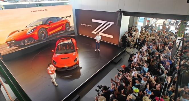
Chinese automotive major BYD Group showcased eight model debuts at the 2026 Goodwood Festival of Speed, where it occupied a 2,016 square metre stand. The display featured vehicles from the BYD, DENZA and YANGWANG brands, with several models participating in the hillclimb event.
At the event, BYD introduced the DOLPHIN G DM-i, a supermini featuring Dual Mode Super Hybrid technology that pairs an electric motor with a 1.5-litre petrol engine. The manufacturer also presented the SHARK pickup, which produces 436PS and accelerates from 0-62mph (0-100 kmph) in 5.7 seconds.
DENZA unveiled the Z sports car, a coupe with 1604PS and a top speed of 217mph (350 kmph), which was presented by Stella Li and 2009 Formula 1 World Champion Jenson Button. The brand also displayed the BAO 5 SUV, which incorporates DMO (Dual Mode Off-road) technology. Additionally, DENZA demonstrated charging speeds of up to 1,500kW, allowing vehicles to charge from 10-70 percent in five minutes.
YANGWANG exhibited the U9 Xtreme, a production car with a top speed of 308.3mph (496 kmph) and a 1200V powertrain. The brand also displayed the U8L SUV and the U7 saloon.
Stella Li, Executive Vice President, BYD, said, "It's been an exciting privilege to play such a central role at this year's Goodwood Festival of Speed. Our stand has been the focal point for thousands of visitors, who've been able to explore a host of new models – our incredible DENZA Z and DENZA BAO 5, as well as the BYD SHARK and, for the first time in the UK, the DOLPHIN G DM-i. We've really enjoyed meeting car enthusiasts from around the world, and it's been a particular thrill to see our cars, such as the YANGWANG U9X, going up the iconic hillclimb. Goodwood really is a global centrepiece for car culture, and we're delighted to have been able to show how our new-energy technologies are creating advances in sustainable mobility around the world."
- IVECO
- PETRONAS Lubricants International
- IVECO URANIA
- IVECO TUTELA
- Domenico Nucera
- IVECO Group
- Domenico Ciaglia
IVECO and PETRONAS Lubricants International Renew Strategic Partnership
- By MT Bureau
- July 12, 2026
European commercial vehicle major IVECO and PETRONAS Lubricants International (PLI) have renewed their strategic partnership for five years, extending the agreement through 2032.
The collaboration continues the supply and joint engineering of lubricants for IVECO’s vehicle portfolio in Europe, including engine oils, transmission fluids, brake fluids and coolants.
The partnership focuses on the development of IVECO URANIA engine oils and IVECO TUTELA technical fluids. These products are recommended by IVECO and result from joint research and development. Recent innovations include the launch of Urania Next 0W-16, a lubricant formulated for heavy-duty applications.
Domenico Nucera, Chief Quality & Operations Officer, Iveco Group, said, "The renewal of the agreement with PETRONAS Lubricants International confirms the strength of a long-standing collaboration built on shared technical expertise and a common ambition to continuously improve performance, efficiency, and sustainability across our vehicle and powertrain portfolio. Through the co-engineering of our IVECO URANIA and IVECO TUTELA ranges, we are able to deliver solutions that maximise vehicle uptime, optimise total cost of ownership, and support our customers and dealer network with the highest standards of quality and reliability."
Domenico Ciaglia, Group Chief Strategy & Transformation Officer, PETRONAS Lubricants International (PLI), said, "This partnership renewal demonstrates what can be achieved through a long-term forward-thinking collaboration, with consistency, and a shared commitment to excellence. Through continuous product innovation, we have been able to co-develop market-leading solutions such as the Urania Next 0W-16 engine oil formulation, seamlessly integrated into IVECO's ecosystem. This collaboration enables us to deliver greater value to the industry by combining our expertise and driving innovation together. Looking ahead, PETRONAS Lubricants International remains fully committed to supporting the IVECO Group with forward integrated reliable, high-performance products and solutions that create lasting value for its network and customers. This renewed collaboration further reinforces the foundation of PLI's broader strategic roadmap, demonstrating how technical excellence and trusted partnerships can drive sustainable, long-term value internationally."
L&T Technology Services Concludes Engineering Intelligence Hackathon
- By MT Bureau
- July 11, 2026
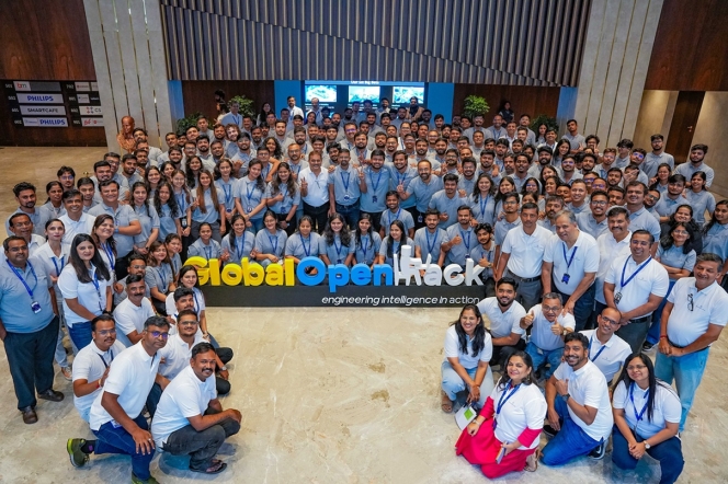
L&T Technology Services (LTTS), a leading engineering research & development (ER&D) company, has concluded its Engineering Intelligence (EI) OpenHack 2026, an innovation challenge held simultaneously across nine locations in India, the US and Europe. The event involved nearly 4,000 engineers across 770 teams.
Participants worked on over 500 challenge statements related to software-defined mobility, plant modernisation, energy, automation and AI infrastructure. The solutions developed during the 24-hour event focused on areas such as industrial automation, cybersecurity, autonomous systems and healthcare.
A jury evaluated the entries based on innovation, technical execution, scalability and relevance. The winning teams received prizes totalling over INR 3 million. Promising projects were selected for further development through the company’s Project Equinox platform and patent-worthy concepts were identified for intellectual property recognition.
Mritunjay Kumar Singh, Chief Operating Officer, L&T Technology Services, said, “The EI OpenHack 2026 reflects LTTS’ vision of Engineering Intelligence, where engineering expertise and AI come together to solve real-world industry challenges. What stood out was not only the scale of participation, but the ability of our engineers to apply contextual understanding, domain knowledge and AI prowess to develop solutions with tangible business relevance. Initiatives like OpenHack create opportunities for our talent to experiment, collaborate and develop solutions that will shape the future of engineering.”
Comments (0)
ADD COMMENT